|
|
|
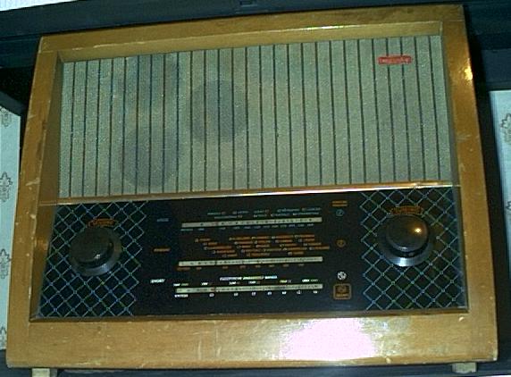
MURPHY A212
MURPHY A212. This nice looking a.c mains valve radio receiver, was introduced in May, 1954.It employs long, medium, & short wavebands. The valve line- up is :- 6C9, 6F15, (or 6F16), 6LD20, 6P25, and a metal rectifier, WESTINGHOUSE 14B986. The set belonged to a work colleague, who asked me to repair it for him. The first thing that I noticed, that there was no sound when I powered up the set, using the "wet-finger" test on the "wiper" part of the volume control. I soon discovered that the output valve, 6P25, had become "gassy", and needed replacement. After replacing the 6P25 valve, I also discovered that the volume control had been incorrectly wired up the wrong way from manufacture, the wiper and the input wire connections had been inverted. This fault, I duly corrected. I then set about checking the resistor ( anode load) to the 6LD20 valve (100k ohm) - this had gone out of tolerance, so this was replaced along with the leaky wax paper audio coupling capacitor, which leads to the grid of the 6P25 valve. Now, I could hear some reaction from the speaker, when I powered up the set, and did the test on the volume control for amplifier operation. The screen by-pass capacitor for the valves, 6C9, and 6F15, had become badly leaky, ( 0.05 uF) and was causing the resistor to sweat. I replaced the capacitor (the resistor was o.k). The resistor (33kohm) for the 6C9 triode section was out of tolerance, so this was also replaced. The radio began to work again, but there was another fault. Murphy liked using the rotary wavechange switch (unused tags), to switch the h.t out of the radio section when the set was used in the gram position. The switch began to spark, as the insulation began to break down. I removed the wires from the switch, and joined them together, and insulated the joint. The radio worked after this, but I wasn't going to let the customer have his set back until I had replaced all the leaky wax paper capacitors - I replace them with high voltage polypropylene types. The metal rectifier was replaced with a BY127 silicon rectifier and a suitable anode resistor to limit current flow.(just in case the metal rectifier became troublesome in the future, since this set was going to be used a lot by the customer). I also checked the mains lead (cotton outer insulation), and this proved to be o.k, but the wires inside were not rubber coated, as first suspected, but were p.v.c insulated, so the lead was suitable. Two new scale lamps were also fitted. The owner was very pleased to have his radio back, and working!